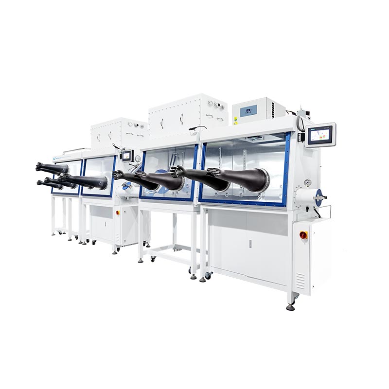
Moving from ambient lab environments to controlled integrated systems represents the critical leap for reliable thin-film device manufacturing. You cannot scale advanced materials without absolute atmospheric stability. Integrating a thermal evaporator or PVD system into an inert environment introduces complex variables. Engineers face sudden hurdles regarding vibration control, thermal load management, and volatile solvent contamination. Exposing multi-layer architectures to ambient room air instantly degrades sensitive compounds. This moisture exposure quickly plunges your overall device efficiency and ruins experimental repeatability.
This guide outlines the engineering realities and core evaluation criteria for selecting a combined processing enclosure and deposition chamber. We explore specific implementation risks across sensitive electronics and photovoltaic workflows. You will learn how to balance ultra-low atmospheric thresholds with modular expansion capabilities. By understanding these integration dynamics, you can safeguard your active layers. Proper equipment selection guarantees highly repeatable baseline efficiencies and protects your research scale-up.
Key Takeaways
Integration limits variables: In-situ processing eliminates vacuum breaks, preventing rapid oxidation of sensitive materials (e.g., Sn(II) to Sn(IV) in perovskites) and particulate contamination.
Application-specific hazards: OLED fabrication prioritizes extreme vibration mitigation and ISO-grade cleanroom control, whereas solar cell production demands robust solvent trapping (DMF, DMSO) and anti-corrosive designs.
Total Cost of Ownership (TCO): Balancing ultra-low atmospheric thresholds (<1 ppm O2/H2O) with operational energy consumption and purifier regeneration cycles is key to sustainable long-term scale-up.
Risk mitigation: Evaluating outgassing, thermal cross-talk, and material re-evaporation (e.g., low-boiling-point precursors) is mandatory before finalizing equipment specifications.
The Business Case for a Fully Integrated Evaporator System
Exposing multi-layer devices to ambient air destroys efficiency. Researchers often transition samples from solution-processing steps to vacuum deposition stations across open laboratory spaces. This brief exposure creates unpredictable yield variations. Atmospheric moisture and oxygen attack sensitive organic layers instantly. You cannot achieve reliable baseline efficiencies if environmental interference variables constantly change. An integrated solution permanently seals the entire process.
Integrating these systems provides several distinct operational advantages. We outline the most significant benefits below:
Unbroken Workflows: You can transition substrates directly from a spin coater or slot-die coater into the thin film deposition chamber. This eliminates vacuum breaks entirely. The inert atmosphere remains perfectly maintained throughout the device assembly.
In-Situ Tooling and Masking: Operators perform in-situ mask changes easily. You can execute multi-source co-deposition without exposing the chamber internals to room humidity. This setup drastically reduces pump-down times compared to standalone external systems.
Enhanced Film Uniformity: You achieve tighter control over film thickness. Removing moisture adsorption from the chamber walls stabilizes the deposition rate. This leads to highly repeatable baseline efficiencies across multiple batches.
A common mistake involves underestimating pump-down delays in standard setups. When you open a standalone vacuum chamber to the room, water vapor coats the internal walls. The vacuum pumps must work for hours to desorb this moisture. Integrated systems open exclusively into a dry, inert environment. This design accelerates high vacuum achievement and boosts daily throughput.
OLED Glove Box vs. Solar Cell Glove Box: Mapping Process Specifics
Different technologies demand unique protective measures. You cannot use a generalized system for highly specialized device architectures. Engineers must map out exact process requirements before requesting equipment specifications. Organic light-emitting diodes and photovoltaic devices share similarities but diverge sharply regarding hazards.
OLED Fabrication Requirements
Successful OLED fabrication requires strict particulate management. Active layers measure only a few nanometers thick. Even microscopic dust particles cause catastrophic pinholes and short circuits. Facilities frequently specify ISO Class 2 cleanroom standards inside the enclosure. High-capacity HEPA or ULPA filters operate continuously to scrub the internal atmosphere.
Vibration control serves as another non-negotiable factor. A dedicated OLED glove box demands advanced anti-vibration platforms. Micro-vibrations generated by circulation blowers or vacuum pumps severely disrupt precision co-deposition. They also ruin physical shadow-mask alignment. Manufacturers decouple heavy vacuum pumps from the main frame to mitigate mechanical resonance.
Solar Cell Production (Perovskite & OPV) Requirements
Photovoltaic workflows introduce entirely different engineering challenges. Solar cell production often utilizes perovskite structures. These materials exhibit extreme atmospheric sensitivity. Trace moisture causes active black phase perovskites to degrade into the inactive yellow phase within minutes. You must maintain strict oxygen and water thresholds below 1 ppm.
Furthermore, these processes present severe chemical and toxic hazards. Precursor inks contain highly corrosive materials. A standard solar cell glove box requires specialized anti-corrosive coatings and robust solvent trapping mechanisms. Standard stainless-steel interiors degrade quickly if left unprotected. Thermal volatility also demands careful management. Low-boiling-point materials like MAI (Methylammonium iodide) require specific thermal controls. Without them, operators face secondary re-evaporation and severe chamber cross-talk.
Comparison: OLED vs. Solar Cell Production Environments
Parameter
OLED Requirements
Solar Cell (Perovskite) Requirements
Primary Sensitivity
Particulates (Pinholes) & Moisture
Moisture (Phase degradation) & Oxygen
Vibration Tolerance
Extremely Low (Affects mask alignment)
Moderate (Standard isolation is often sufficient)
Chemical Hazards
Low to Moderate (Mostly solid organics)
Extremely High (Corrosive solvents, toxic precursors)
Thermal Management
Standard substrate cooling
Crucial for low-boiling-point precursors (e.g., MAI)
Critical Evaluation Criteria for an Evaporator Glove Box
Selecting the right equipment requires rigorous vendor scrutiny. You must look beyond standard marketing claims. Engineers should demand realistic performance metrics under active processing conditions. Let us review the primary evaluation criteria.
Atmospheric Purity & Filtration Mechanisms
Baseline capabilities must maintain O2 and H2O levels below 1 ppm during active operations. Many systems achieve these metrics in static states but fail during process transfers. You should evaluate HEPA and ULPA filtration specifications closely. Critical applications often require filtering particulates down to 0.12μm. Continuous gas circulation prevents dead zones where contaminants might accumulate.
Deposition Chamber Interoperability
Integration mechanics dictate overall system reliability. You must assess how the vacuum system, gas inlets, and antechambers share infrastructure. Poor designs cause sudden pressure imbalances during pump-down cycles. These imbalances rupture gloves or disturb delicate powders. Evaluate the system's compatibility with multiple PVD methods. Ensure it accommodates thermal evaporation, sputtering, and atomic layer deposition (ALD) modules without major retrofits.
Energy Efficiency & ESG Compliance
Modern laboratories prioritize Environmental, Social, and Governance (ESG) compliance. Traditional systems run blowers at maximum capacity constantly. This generates massive power waste. Look for automated energy-saving modes. Variable frequency drives (VFDs) for blowers drop power consumption significantly during idle hours. Smart sensors detect inactivity and scale back circulation speeds. This intelligent regulation aligns with sustainable laboratory practices and minimizes carbon footprints.
Evaluation Matrix Chart for Integrated Systems
Evaluation Category
Key Metric to Verify
Ideal Benchmark
Atmospheric Purity
Active operation O2/H2O levels
< 1 ppm sustained
Filtration Standard
Particle size capture
0.12μm (ULPA grade)
Energy Efficiency
Idle mode power consumption
Automated VFD step-down
Interoperability
Pressure differential management
Automated balancing during transitions
Implementation Risks: Outgassing, Thermal Loads, and Solvents
Hardware integration carries specific process risks. You cannot simply bolt a vacuum chamber to a steel box. Process engineers must anticipate chemical and thermal clashes. Overlooking these risks leads to ruined catalyst beds and contaminated thin films.
The Solvent Trap Necessity
Wet-processing steps heavily utilize organic solvents. Precursors containing DMF, DMSO, or chlorobenzene off-gas intensely during spin coating and annealing. These solvent vapors will rapidly poison the gas purifier's copper catalysts. An automated, regenerable molecular sieve solvent trap represents a strict prerequisite. Without it, you will lose atmospheric control entirely. Integrating a high-capacity solvent trap protects the primary purification loop and extends system lifespan.
Material Outgassing in High Vacuum
Materials behave differently under extreme vacuum. You must evaluate the risk of materials releasing trapped gases inside the integrated system. We call this phenomenon outgassing. Porous components, specific plastics, or improperly baked-out substrates release moisture and hydrocarbons. This sudden gas load spikes chamber pressure unpredictably. It directly contaminates growing thin films, ruining their electrical properties. Best practices dictate using ultra-high vacuum (UHV) compatible materials throughout the transfer mechanisms.
Thermal and Vacuum Leak Management
Thermal evaporation processes generate intense radiant heat. You must identify proper fail-safes for the heat generated by the evaporator glove box. Water-cooled shielding prevents thermal transfer to the inert atmosphere. Overheating causes safety interlocks to trip, halting production. You must ensure robust safety mechanisms exist. Systems need routine automated leak checks. They must feature positive pressure maintenance capabilities to protect the environment during an accidental glove rupture. Additionally, integrate UV-blocking window coatings to shield sensitive organic compounds from ambient laboratory lighting.
Scaling Up: From Single-Junction Lab Research to Tandem Cells
Research programs rarely stay static. Your equipment must adapt to evolving architectures. Investing in rigid, non-upgradable hardware severely limits future development. Scaling device area and complexity requires thoughtful equipment modularity.
Modularity for Future Workflows
Single-station setups often become sudden bottlenecks. When research expands, you need more throughput. Evaluate systems capable of modular expansion. You should be able to bolt on additional transition antechambers easily. Future workflows might require attaching secondary process modules or dedicated encapsulation units. Standardized flange connections ensure you can upgrade your setup without completely decommissioning the existing footprint.
Transitioning to Tandem Cell Production
The photovoltaic industry relies heavily on stacked architectures. As research moves toward tandem cells, the required process steps multiply rapidly. A standard tandem cell might combine a Silicon or CIGS bottom layer with a highly sensitive perovskite top cell. This complexity demands multi-chamber scalable systems. You need continuous lines that can house spin coaters, thermal stages, and solar simulators.
All these stations must operate seamlessly alongside the main evaporator system. A modular integration approach allows you to transfer a silicon bottom cell directly into the inert environment. You then deposit the perovskite layers and top contacts without ever breaking atmospheric protection. This scalable methodology provides the only viable path toward commercializing next-generation tandem photovoltaics.
Conclusion
Integrating thin-film deposition hardware with inert atmosphere control is not merely about joining two pieces of equipment. It is about actively mitigating cross-contamination, thermal stress, and volatile chemical damage. Reliable device fabrication requires unbroken workflows and strict management of both particulates and hazardous solvents. You must evaluate systems based on their interoperability and their ability to sustain sub-ppm purity during active coating processes.
Prioritize vendors who offer transparent data on solvent trapping efficiency, vibration mitigation, and realistic energy consumption. Define your specific material constraints clearly before requesting a customized system footprint. Identify corrosive precursors or multi-layer masking requirements early in the planning phase. By addressing outgassing risks and planning for tandem cell modularity today, you guarantee a scalable, high-yield manufacturing process for the future.
FAQ
Q: Why is an integrated solvent trap necessary for a solar cell glove box?
A: Wet-processing steps in solar cell fabrication use volatile organic solvents (like DMF or chlorobenzene). Without a trap, these solvents circulate and permanently degrade the copper catalyst in the purification system, causing atmospheric control failure.
Q: Does integrating the thin film deposition chamber affect pump-down times?
A: Positively. Because the chamber opens into a dry, inert environment (rather than ambient, humid room air), water vapor is not adsorbed onto the chamber walls, significantly reducing the time required to achieve high vacuum.
Q: How do we handle low-boiling-point materials like MAI in thermal evaporators?
A: Standard thermal evaporation often leads to material bouncing or re-evaporation. Specialized systems use temperature-controlled internal walls and specific low-temperature evaporation sources to stabilize the deposition rate.
Q: What is the recommended vibration control for OLED glove boxes?
A: Systems should feature decoupled vacuum pumps and heavy-duty anti-vibration framing to prevent mechanical resonance from translating to the substrate, which is critical for precision shadow-mask alignment.